TPU Architecture
Core Components
A TPU is essentially a specialized compute core for Matrix-Multiplication attached to fast memory. The main components are:
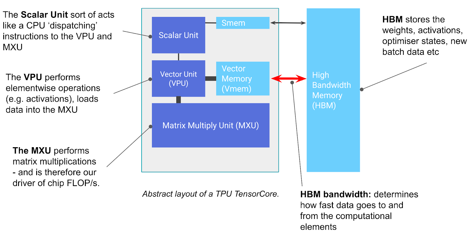 Figure: Basic components of a TPU chip showing the TensorCore (left gray box) and HBM (right). Source: How to Scale Your Model
TensorCore
The TensorCore contains the following main units:
- MXU (Matrix Multiply Unit):
- Core component that performs matrix multiplication
- Uses a systolic array architecture
- Performs one
bfloat16[8,128] @ bf16[128,128] -> f32[8,128]operation every 8 cycles - TPU v5e: ~5e13 BFloat16 FLOPs/s per MXU
- TPU v6e (Trillium): Uses a larger 256x256 systolic array
- Each tensor core has 2-4 MXUs:
- TPU v5p: 2.5e14 bf16 FLOPs / second (per core) or 5e14 bf16 FLOPs / sec (per chip)
[! info] MXUs use Systolic-Array for fast matmuls, read more at corresponding note
-
VPU (Vector Processing Unit):
- Performs general mathematical operations (ReLU, addition, multiplication)
- Handles reductions (sums)
- 2D vector machine of shape (8, 128) - (lane, sublane)
- Contains 2048 floating point adders on v4
-
VMEM (Vector Memory):
- On-chip scratchpad close to compute units
- Much smaller than HBM but higher bandwidth
- Programmer-controlled (unlike traditional CPU caches)
- TPU v5e: 128 MiB capacity
- Similar to L1/L2 cache but larger
-
HBM (High Bandwidth Memory)
- Large, fast memory storing tensors for use by TensorCore
- Typically tens of gigabytes capacity (TPU v5e: 16GB)
- Data flows: HBM → VMEM → compute units → VMEM → HBM
- Bandwidth between HBM and TensorCore (1-2TB/s) determines performance limits for Memory-Bound workloads
TPU Performance Characteristics
- Pipelined Operations: All TPU operations are pipelined and overlapped
- Matrix Multiplication Focus: TPUs are optimized specifically for matrix operations
- VMEM and Arithmetic Intensity: With data in VMEM instead of HBM, operations can be Compute-Bound at much smaller batch sizes
 Figure: Data and Compute Flow for point-wise operation in TPU. Source: How to Scale Your Model
[! Info] Takeaway TPUs are simple devices that load weights from HBM into VMEM, then into a systolic array for computation. The HBM ↔ VMEM and VMEM ↔ systolic array bandwidths determine fundamental performance limits.
TPU Organization
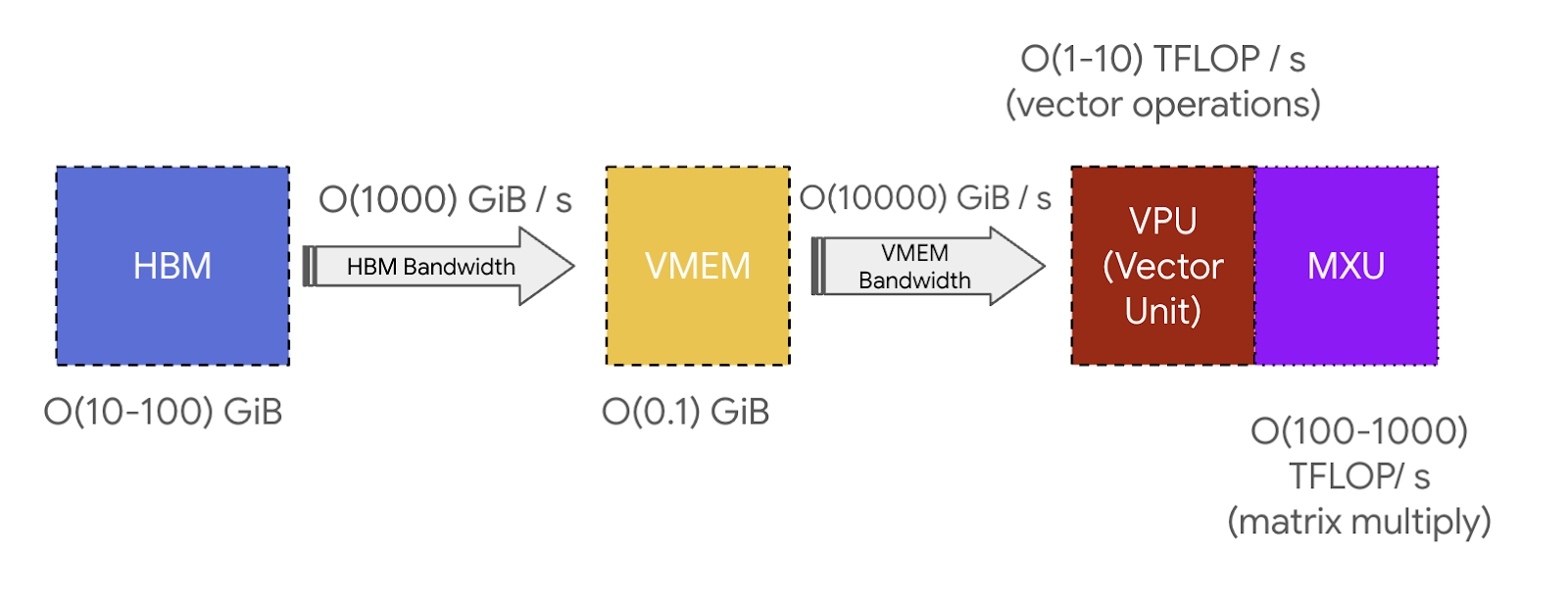 Figure: Memory and Bandwidth hierarchy in TPU. Source: How to Scale Your Model
-
Core/Chip Structure:
- TPU v4+: Each chip typically has two cores sharing memory (“mega core” configuration)
- Inference chips (TPU v5e): One core per chip
-
Tray Organization:
- 4 chips per tray connected to a CPU host via PCIe
- Standard configuration for Colab or TPU-VM (4 chips = 8 cores or 4 mega cores)
- Inference chips (TPU v5e): 2 trays per host = 8 chips = 8 cores
-
PCIe Connection:
- Links CPU host to TPU tray
- Limited bandwidth (~16GB/s for TPU v4)
- ~100x slower than HBM
TPU Networking
ICI Network
-
ICI (Inter-Chip Interconnect): Direct links between chips
-
Topology:
- TPU v2/v3/v5e/v6e: 4 nearest neighbors (2D torus)
- TPU v4/v5p: 6 nearest neighbors (3D torus)
- Toroidal structure reduces maximum distance between nodes
- “Twisted torus” configuration further reduces average distance
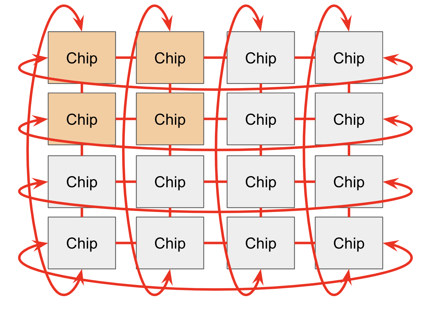 Figure: TPU ICI connections with wraparound links forming a torus structure. Source: How to Scale Your Model
Pod Organization
-
Building Blocks:
- Composed of reconfigurable 4x4x4 cubes
- Connected by optical wraparound links (ICI)
- Smaller topologies available (2x2x1, 2x2x2) but without wraparounds
-
Pod Size:
- TPU v4: 16x16x16 maximum (superpod)
- TPU v5p: 16x20x28 maximum
- TPU v5e/v6e: 16x16 maximum (2D torus)
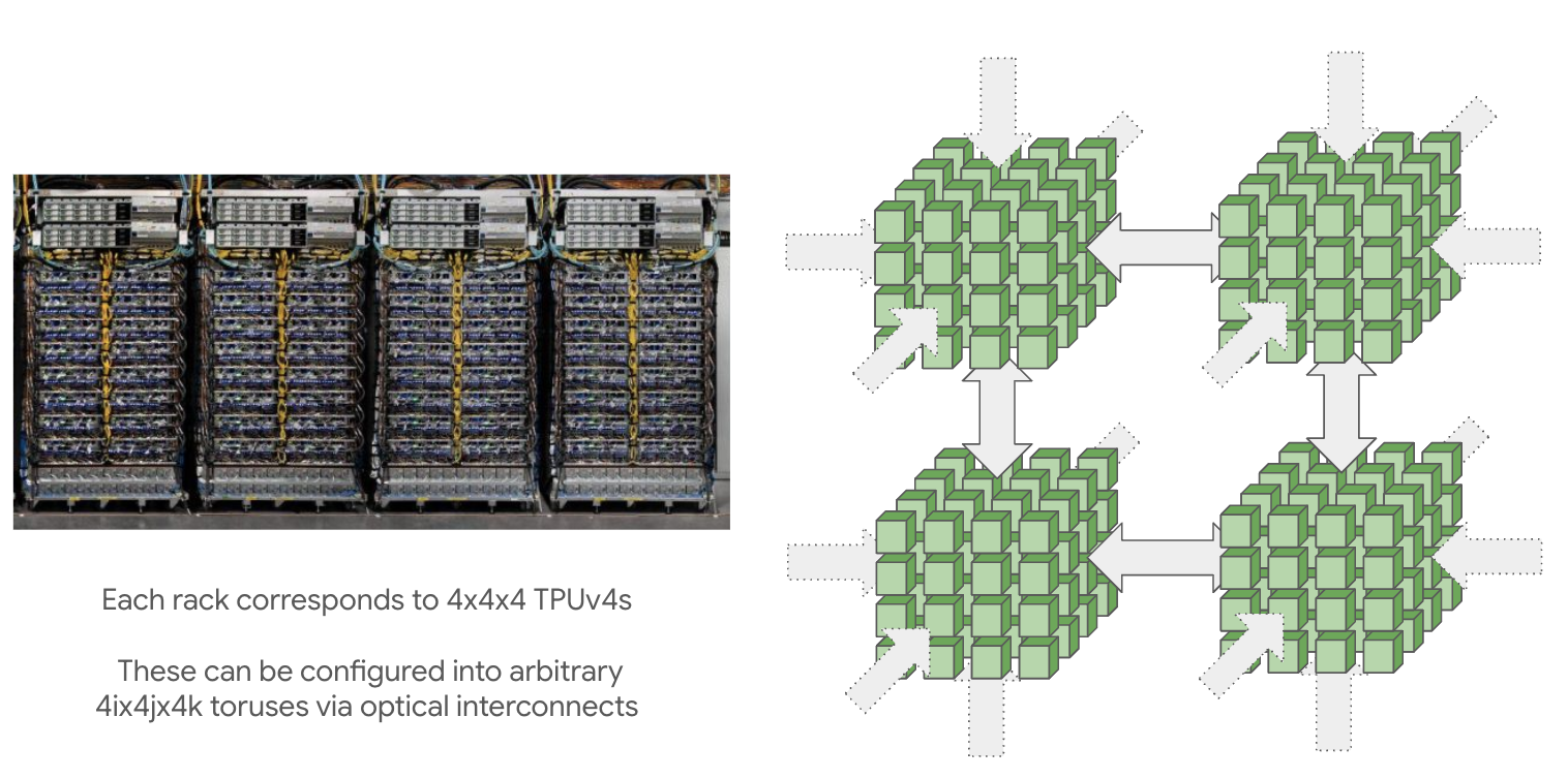 Figure: A 16x16x16 TPU super pod made up of 4 4x4x4 pods. Source: How to Scale Your Model
-
Slices: A set of ICI-connected TPUs is called a “slice”. Pod is the maximum slice for a given topology (e.g. 16x16x16 for TPU v4)
the difference between a pod and a slice is unclear to me
Communication Hierarchy
ICI vs HBM Bandwidth: ICI is fast but still slower than HBM
- TPU v5p: 2.5 TB/s HBM bandwidth vs 90 GB/s ICI bandwidth per axis (25x difference)
- Careful partitioning needed to avoid bottlenecks when splitting models across chips
Communication (off Tensor core) is limited by network bandwidths, in order of speed:
- HBM bandwidth: Between TensorCore and associated HBM (fastest)
- ICI bandwidth: Between a TPU chip and nearest 4-6 neighbors (fast)
- PCIe bandwidth: Between CPU host and associated tray(s) (slower)
- DCN bandwidth: Between multiple CPU hosts not connected by ICI (slowest)
Single-slice training: Within a slice, TPUs are only connected to nearest neighbors via ICI, meaning communication between distant chips must hop through intervening chips.
Multi-slice training: Different slices connect via DCN (much slower than ICI)
TPU vs GPU Networking Differences
- TPUs: Nearest-neighbor connectivity, scales to larger topologies with constant links per device
- GPUs: All-to-all configuration within a node (up to 256 H100s), more expensive to wire together
TPU Specifications
| Model | Pod size | Host size | HBM/chip | HBM BW/chip | FLOPs/s/chip (bf16) | FLOPs/s/chip (int8) |
|---|---|---|---|---|---|---|
| TPU v3 | 32x32 | 4x2 | 32GB | 9.0e11 | 1.4e14 | 1.4e14 |
| TPU v4p | 16x16x16 | 2x2x1 | 32GB | 1.2e12 | 2.75e14 | 2.75e14 |
| TPU v5p | 16x20x28 | 2x2x1 | 96GB | 2.8e12 | 4.59e14 | 9.18e14 |
| TPU v5e | 16x16 | 4x2 | 16GB | 8.1e11 | 1.97e14 | 3.94e14 |
| TPU v6e | 16x16 | 4x2 | 32GB | 1.6e12 | 9.20e14 | 1.84e15 |
ICI Bandwidth:
| Model | ICI BW/link (one-way) | ICI BW/link (bidirectional) |
|---|---|---|
| TPU v3 | 1e11 | 2e11 |
| TPU v4p | 4.5e10 | 9e10 |
| TPU v5p | 9e10 | 1.8e11 |
| TPU v5e | 4.5e10 | 9e10 |
| TPU v6e | 9e10 | 1.8e11 |
Other Bandwidths:
- PCIe: ~1.5e10 bytes/s per chip (TPU v6e: 32GB/s)
- DCN: ~2.5e10 bytes/s per host
Key Optimization Considerations
Matrix Dimensions: Weight matrices need to be padded to at least size 128 (256 on TPU v6e) in both dimensions to fill the MXU
Precision Tradeoffs: Lower precision matrix multiplication is faster
- INT8/INT4 operations are 2x/4x faster than BF16 operations
- VPU operations still use FP32
Communication Balance: Ensure amount of communication across each channel is proportional to its speed
MXU Efficiency: For maximum throughput, ensure dimensions match or exceed MXU size